But why though?
Every FRC team has at least one CAN bus, but in the era of CAN sensors galore, COTS swerve with CAN encoders, and 20 motor slots on the REV Power Distribution Hub, it's worth a look into strategically using your CAN bus for when utilization gets high.
Warning: This topic may be educational, but changing the discussed items without as much knowledge as possible may result in a robot that works worse than when you started, or is more dangerous. This article is not intended to be exhaustive. Be careful.
The CAN bus on the roboR1O & RoboRIIO is a 1Mbps bus running on two wires, terminated at either end with a 120Ω resistor (one inside the roboRIO, one in the PDP/PDH). Messages are sent out, and every device on the bus must recieve it, even if it does nothing with it. CAN is resilient in the sense that inducted line noise (motors, other voltage, etc.) doesn't significantly interfere with the transmission of data. This is significantly different than things like quadrature encoders or limit switches, where line noise may trigger false positives on reads.
When sending a command on the CAN bus (such as commanding a motor's speed), a message is sent from the roboRIO to the CAN bus, seen by all devices on that bus, and executed on by particular motor or device.
Reading a status update, such as the motor temperature on a Spark Max, is free and does not consume additional bus bandwidth. This is because of status frames being sent out at a regular interval (more on this later), and while minute technical details aren't super important generally, they can be when assumptions fall aprt and CAN doesn't work as intended.
A disconnect anywhere in your CAN chain will result in devices going missing, and a crossed wire will result in everything after the crossed wire vanishing from the bus, potentially causing many control issues. The subtle issue of CAN utilization is less obvious. While it's a 1Mbps bus (otherwise known as CAN 2.0B spec), reflectance (when the signal being sent bounces back) as well as a multitude of electrophysical effects, cause the CAN bus to not work as well once you exceed approximately 85% utilization.
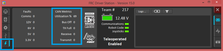
Per the Crossing The Road Electronics documentation though, a mere 16 motor controllers (Talon SRXes), a CTRE Pneumatics Control Module, and a Power Distribution Panel, will result in 70% utilization.
Some extrapolation of this neatly tells us that 20 motor controllers will get us to 87%, and additional sensors push it even more. How can we mitigate this to avoid potential controls issues?
Status frames are how the motor controllers typically used in FRC announce to other devices on the CAN bus what they're doing and what their overall status is. This enables us to use features like motor controller following to only need to command one motor controller, rather than as many as you have moving together. The rates at which these messages are sent out is largely configurable, and certain configurations of motor controller have no need for certain status frames.
If we take a look at the Spark Max docs in the CANSparkMaxLowLevel class, we can find the SetPeriodicFramePeriod() function, that takes in a PeriodicStatus{0,6} object. What does each one do though, and where can we find them?
REV exposes these as attributes of the PeriodicStatus{0,6} classes, and below are a sampling of the categories. Checking the documentation reveals all of these, and the default period.
    struct PeriodicStatus0 {
        double appliedOutput;
        uint16_t faults;
        uint16_t stickyFaults;
        MotorType motorType;
        bool isFollower;
        uint8_t lock;
        uint8_t roboRIO;
        uint8_t isInverted;
        uint64_t timestamp;
    };

    struct PeriodicStatus1 {
        double sensorVelocity;
        uint8_t motorTemperature;
        double busVoltage;
        double outputCurrent;
        uint64_t timestamp;
    };

    struct PeriodicStatus2 {
        double sensorPosition;
        double iAccum;
        uint64_t timestamp;
    };
The first group is the most important, and as such, is why REV defaults to sending it out at 10ms (100Hz). We're unlikely to change this one. The second group contains sensor velocity (encoder), temperature, bus voltage (battery voltage reaching the motor controller), and output current. In the event of using a Spark Max to drive a brushed motor (for example), we will not need the majority of this data. As such, as can configure it to transmit status frames less frequently.
The third group is the least used. containing only sensor position, integral accumulation (internal to the PID controller), and the timestamp of the status itself. This one is rarely used and is very unlikely to be a major issue given it contains significantly less data than the other two groups.
The same logic as above applies to CTRE devices, as outlined in their documentation. I'll spare the minutae of it, given that CTRE has outlined 11 groups for motor controllers, 9 for IMUs, and 6 for the CANifier. Reading through the frame periods on a device by device basis may call out frame periods that you can safely change. keep in mind the eqivalent function will be called differently. The equivalent function in their documentation can be (at time of writing) found here.
While REV offers a frame period of up to 65536ms, or more than a minute between frames, CTR opts to only allow a status frame delay of up to 255ms. CTR's solution tends to inclinate teams to use of a CANivore, a higher speed CAN-FD bus adapter, but that only works with some modern CTR products, leaving teams with other products with these difficulties still. One still can and should be aware of bus utilization of CANivore buses, as it won't report in the Driver Station. See how here.
For more information on CAN-FD, please refer to these links from CTR's website.
So now we know how we can adjust the timing period for CAN devices we tend to use a lot. But are there other methods we can think about the bus congestion problem. Because we're likely to use different mechanisms in FRC at different points in a match, we can actually tell our mechanism startup to change the status frame period as needed. For example, a climb mechanism probably doesn't need to be at maximum update rates when you're firing fuel cells into the goal, and vice versa.
If you are encountering issues then this might be a good set of variables to experiment with, but you are not likely to see a performance improvement and you should use caution when changing these values. This can help resolve some CAN utilization issues but when done incorrectly can render your robot very nerfed or be dangerous.
- Kim